| |
|
|
| |
|
Back to main page |
Niklas Roy's Gallerydrive wheelchair modifying and Galleryzone development diary |
|
|
| |
|
|
| |
|
|
|
First of all, this is a diary and not a weblog. You'll find the earliest entries on top, and the most recent information at the bottom of this page.
This diary documents, how I turned an electric wheelchair (Meyra "Sprint", Model 1.592) into an automatic Gallerydrive car and how I developed and built the Galleryzone system, which organizes how several cars drive inside a Gallerydrive course.
The Galleryzone system is highly flexible, scalable and modular. If you decide to build your own Gallerydrive car, based on the information, written down in this diary, your car will be able to drive together with my and other cars in the same Gallerydrive exhibition setup. Currently, Volker Morawe and Tilman Reiff of the Cologne and Amsterdam based artist group //////////fur//// also build their Gallerydrive car. They are publishing their experiences on a weblog which is not accessible for the public, yet. |
|
|
| |
|
|
 |
|
Videos
|
|
If you just want to have a general idea of the project, the navigation lines on the left side help you to find diary entries that might interest you. |
|
|
|
Interactive
|
|
|
Galleries
|
|
|
| |
|
|
| |
|
If you also want to build your own Gallerydrive car, and if you are seeking more technical related entries, the navigation lines on the right side will lead you to the required information. (Even if I recommend to read the complete diary in this case.) |
|
Codes
|
|
|
|
|
|
|
|
Plans & Schematics
|
|
|
|
|
|
|
|
PDF's
|
|
|
 |
| |
|
|
| |
|
|
|
The finished Gallerydrive car has the following features:
- A line detection, known from line following robots, which lets the wheelchair drive autonomously on a track of adhesive tape. This track can either be black or white, depending on the grayshade of the floor.
- A touch screen display to inform the visitor, who sits on the car, about the artworks. The touch interface can also be used for interaction with the artworks.
- A mp3-player with closed headphones. This audio player provides a soundtrack for the ride through the exhibition.
- A RFID reader, to let the wheelchair perform different actions, when it passes a RFID tag. Those actions can be the change of driving speed, the change of display content, the change of the currently played mp3-track, and so on...
- A bidirectional RC5-based infrared communication to transmit various information between car and course (or artwork).
- An infrared distance measurement sensor to let the car be able to queue in a row of Gallerydrive cars.
|
|
|
  |
| |
 |
|
7.1.2006
The whole thing starts - of course - with an electric wheelchair. I have won this ugly thing at an Ebay auction for almost no money. The condition of this wheelchair was as bad as the description in the auction was. I guess, that this might have been the main reason, why I was the only one, who wanted to buy it.
View screen shot of the Ebay auction |
|
|
| |
|
   |
|
| |
 |
|
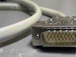
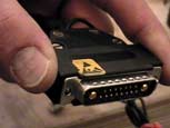
3/2006
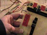
I've built a SUB-D adaptor to find out, how the control unit and the motor driver communicate. This hardware hacking device is also quite useful to try out several test circuits.
Read more and watch photos |
|
|
|
|
|
|
| |
 |
|
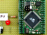
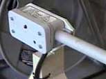
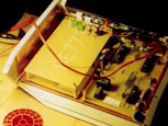
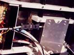
30.3.2006
I've built a 1st control board. It connects a microcontroller to the wheelchair. The controller generates two PWM's (pulse width modulated voltages) - one for steering and one for driving. The board converts them into two control voltages for the motor drivers. This board also controls the "Totmann" (safety) circuit of the motor driver.
Read more and watch photos
Download layout |
|
|
|
| |
 |
|
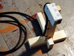
3/2006
This is the 1st draft of a line detection unit. With this device, I want, that the wheelchair detects a line, that I have adhered on the floor. Although it works, you can see in the video from 31.3. that it does not work well enough. So I have to spend more time in building a more precise device.
Read more and watch photos |
|
|
 |
| |
 |
|
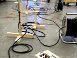
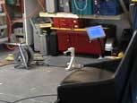
31.3.2006
Have a look at the video of the 1st automatic test run, which happened in my workshop.
Watch video |
|
|
 |
| |
 |
|
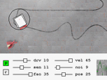
4.4.2006
The last days, I wrote a small program to simulate, how different parameters of the hardware would affect the motion of the wheelchair. One advantage of a simulation is, that crashes don't cause any serious trouble. But the disadvantage is, that simulated crash's are not spectacular at all.
Try out the program
|
|
|
| |
| |
 |
|
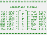
1.5.2006
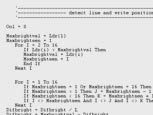
To read out all the voltages, that the controller gets from the advanced line detection device, I want to use the PCF8591 IC from Philips. It is a chip, with four ADC's and one DAC - and it communicates via I²C. So, with four of them, I want to read out an array of 16 LDR's. Perhaps, I will use the DAC's as well, to generate the control voltages. This could be more elegant, than doing it via smoothed PWM. I wrote a code in BASCOM to read out the ADC's of the PCF8591.
Download Bascom code
Download PCF8591 data sheet
Download I²C specifications
Segor electronics distributes the PCF8591 in Germany
Philips has a nice page to find other I²C components |
|
 |
|
| |
 |
|
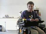
21.5.2006
I made a video of the 2nd automatic test run. For this, I've used the new line detection unit with 16 LDR's. They are read out by four PCF8591, as I wanted to do it. The new circuit also uses three of the PCF8591 DAC's to generate the two control voltages, plus the reference voltage for the motor driver. The software is based on a PID-controlling algorithm, running on an ATMega8. At the moment, I can set the P, I and D values - as well as the driving speed - with potentiometers. At the end of the video, when I'm sitting down, the batteries of the wheelchair were already quite empty, so you can see me increasing the speed value.
The PID controller works really good - as long as the values fit to the weight of the person, which sits on the wheelchair. So the velocity of the system changes with the weight of it. And if there's no one (or maybe a child) sitting on the chair, the P-parameter has to be much lower, than if I am sitting on it. Otherwise, the wheelchair starts to oscillate until it loses the track. And if I am sitting on it - and the P-level is adjusted to the empty chair, the wheelchair will lose the track in the curves. So, perhaps I will need a clever solution, to adapt the values to the different weights of the visitors, using the system.
I also found out, that it will be useful to design a track where all curves have the same radiuses - this makes the PID-adjustment a lot easier.
The next days, I will upload the board-layout and the code, that I used for this test drive.
Watch video
Good (German) source for understanding PID-controllers
PID-controller explained in english |
|
|
| |
| |
 |
|
23.5.2006
Here's the layout of the I ²C control board, that I used to read out the new line detection unit, and with which the control voltages are generated.
Download PDF |
|
|
| |
| |
 |
|
23.5.2006
The new Bascom codes are now available! It is not only the PID-code to control the wheelchair, but also two programs to adjust the LDR-array and one to check the LDR-array. The wheelchair in the last video (from 21.5.) is running with this PID-control and with the board, that I mentioned in the diary entry above.
The adjustment of the LDR-array is maybe not really necessary, but of course, not all the LDR's match exactly in their contrast recognition characteristics. So at least, I wanted to adjust them to the same black and white level. You will see, how it works, when you have a look into the codes.
To adjust the LDR-array (LDU), you have to run the "adjust-black level"-code first. This code writes some code into the terminal window, which you have to copy and paste into the other programs. Then, you have to run the "adjust white level"-program. This also produces some code, which has to be copied and pasted into the PID-controller code and into the code for checking the adjustments.
In the final version, I want to have something like a self-check feature, which will make this annoying procedure obsolete.
Download Bascom PID-controller code
Download Bascom code to adjust black level
Download Bascom code to adjust white level
Download Bascom code to check adjustments |
|
|
| |
| |
 |
|
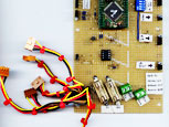
26.5.2006
I have enhanced the board from 23.5.06. Now it has the additional feature, that the error feedback, coming from the motor driver, can be read out by the microcontroller. The error signal (called "Störung" in the original Meyra schematics), which is coming from the motor driver is a 0.8V pulse. Depending on how often the voltage pulses, the kind of error can be determined.
Of course, the 0.8V level is quite useless for reading it out with the controller (I don't want to waste an ADC for that). So, I enhanced it to a TTL-level by a previously unused OpAmp of the LM324.
I also decided to build a new LDR array with 32 LDR's. I will keep this board and enhance it by an additional board with four more PCF8591 to convert the additional 16 voltages. This board should also contain the AtMega8, which controls the driving process.
Although, the Line Detection Unit with 16 LDR's worked already quite well in my last test, I found out, that if I put the LDU under the wheelchair, the position is (mechanically) much safer and the wheelchair does not leave of the track so easy. But because the distance between the rotating point of the wheelchair and the LDU is now just half as long, the precision of the LDU is just half as good. The result is, that the wheelchair starts to oscillate in a very high frequency (this has to do with the high D-factor of the PID-controller and the low precision of the LDU). I guess, the whole system will work really well with that new LDU.
Download PDF |
|
|
|
| |
 |
|
27.5.2006
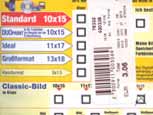
Today, I have been at my local drugstore to pick up the latest photos, that I have made with my old school Nikon, when I was working on the wheelchair during the last months.
Watch photos |
|
|
|
| |
 |
|
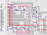
7.6.2006
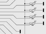
Here are the latest plans for all the circuits, that I've recently built. The LDR-array works, and I guess, that this third version should be finally good enough to be used for the wheelchair. However, during the building, I found out that it might be better to use photo diodes (in LED packages) instead of the LDR's. Because they are cheaper, and they are easier to adjust parallel (if you drill the 5mm holes in the PVC a bit deeper, you can just push them into the holes). The circuit would stay like the same, but because the photo diodes are polarized, their short leg would have to go to +5V (not to -5V!). And I didn't check, which resistance value would have to be used for the voltage divider. You will have to check that on your own, if you decide to replace the LDR's by diodes. The 100nF capacitor should stay. It's purpose is to smooth the signal, which comes from the photo sensors. I am using a cold cathode tube to light the floor, and this flickers in a very high frequency. However, the frequency is not high enough, that the photo sensors wouldn't measure it. So without the capacitors, the analogue voltage which is going to the DAC's would oscillate.
I also designed a second board with four more PCF8591 to get rid of the additional 16 sensors. On that board, there will be the ATMega8, which controls the whole driving process. This controller will communicate with another controller, that cares about the onboard entertainment system and which controls the whole dramaturgy of the ride. There's also a plan for the pin I/O of the drive controller.
Plan of LDR-array (PDF)
Watch photos of the finished piece
Schematics of drive control boards (PDF)
(There is a mistake in board #2 -- please download the board layout from 6.7.2006!)
Pin I/O ATMega8 drive control (PDF)
|
|
|
|
| |
 |
|
18.6.2006
My drugstore has developed another two films for me. The pictures show a lot of the stuff, that I have described in the entries above and some of the images show a bit more...
Watch photos |
|
|
| |
|
|
|
| |
 |
|
7.7.2006
For debugging, I've bought a TVT-MBKD-11 terminal controller. It is a pre programmed Atmega8, which converts serial signals into a video signal. So I can see at a glance, which value the variables in my drive controller have. You can read more about this, or watch the device in action in my latest video.
Read more
Watch video
Webpage of the TVT-MBKD-11 manufacturer |
|
|
|
| |
 |
|
11.7.2006
Now, I let the computer design the track with "Gallerycurve"!
I am waiting for new electronic parts for the wheelchair, so I used my time to write a program, that I already wanted to hack some weeks ago. It is a small Processing code, which draws clothoid curves. Those curves don't have one radiant, but start with an infinite radiant, decrease it linear and increase it linear, when the middle of the curve is passed. In fact, the curves that my program generates don't de- and increase the radiant linear. I mapped a sine-function onto it to make them even more smooth. The purpose of such a curve is, that if the car drives into it, it starts to steer very soft at the beginning point of the curve. Then it steers more and more, and from the middle of the curve on, it decreases the steering smoothly.
Those kind of curves are used for roads and railroads, but also for roller coaster loopings.
The program works quite simple: You can adjust the angle of the curve with the first slider from left. Then, you adjust the length of the curved track with the second slider. The third slider is used to adjust the distance between turning point of the wheelchair (where the odometer wheel is located) and the LDR array. Then, you get two curves: The black curve is what you will have to adhere on the ground. The red path is the clothoid curve. During driving, the turning point of the wheelchair will follow this red path. The minimal radiant of the curve is displayed in the lower left corner.
When you have edited your curve, simply make a screen shot and paste it into Photoshop. Now, set the DPI of the document to the DPI displayed in the lower left corner. Only change the DPI, don't render the image new! Now, you have the curve in the right scale on your computer. I am sure, you'll find a nifty way to print it out in the original size ;-) To find out, if the size of the print is correct, simply check the blue squares. The small light blue squares should have the size 10cm * 10cm, the dark blue should have the size 1m * 1m.
Run gallerycurve program
NASA page about clothoids and rollercoasters...
large collection of links about amusement park physics |
|
|
|
| |
 |
|
14.7.2006
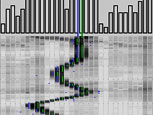
The diagram on the left looks like the latest development of the Gallerydrive Inc. shareholder value. But it isn't. Today, I did an interesting long time test, where I let the wheelchair drive for several hours without changing anything at the PID or speed controller. I clocked every round automatically and wrote a script, which has drawn the times in two diagrams.
First of all, I was very happy, how smooth the wheelchair ran on the track with the clothoid curves, and I was also very delighted, that it didn't lose its track one time during more than three hours of continuous driving.
Watch diagrams |
|
|
|
| |
 |
|
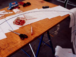
24.7.2006
I have uploaded a series of photos about a clothoid template, that I have built. With that 1:1 scale template, I have adhered a new track in my floor, which works pretty well.
Watch photos |
|
|
|
| |
 |
|
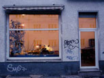
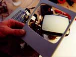
24.7.2006
One important part of the Gallerydrive car, will be its display. And finding the right style of display is a hard job. First, I wanted to use a black and white CRT. Now, I will use a blue and white LCD. To find out, what changed my mind, ...
...read the CRT story! |
|
|
|
|
|
|
| |
 |
|
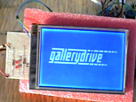
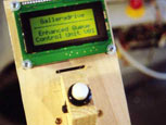
18.8.2006
As I announced on 24.7., I will use a nice blue LCD display with touch screen, for the wheelchair. Now, I have done the first tests with it. Its exact name is "eDIP 240-7", and it is produced by Electronic Assembly. The display has a resolution of 240*128 pixels, no gray scale, and an analogue touch screen. It can be interfaced via RS232, I²C and SPI. The display has its own microcontroller, where you can store macros, bitmaps and additional fonts. You can write the macros and design the images and fonts on a windows PC with a free software, which can be downloaded at the Electronic Assembly webpage. To upload it to the display, either a self built RS232 adaptor is required, or an USB cable, which you can order at EA. I used the self built RS232 adaptor and it worked well.
The interfacing between my controller and the display happens via I²C. Once I've found out, how it goes, it works alright. But I had to spend the last three weeks to get all the features running. For the interfacing, the display normally uses a protocol, called "smallprotokoll". While the name "smallprotokoll" is already a strange mixture between English and German, the protocol is also not so convincing. According to the data sheet, the disadvantage of not using this protocol is, that you can't recognize any overflows at the display's input buffer. But when I tried it out and sent a lot of data in short time to the display, using this protocol, the whole hardware stalled. So it seems, that I have to take care, that I don't send too many data in too short time to the display, anyway. But then, there is no need for the protocol anymore. So, I finally switched the smallprotokoll off by closing the solder bridge J2.
Download a zip archive with Bascom code, macros, bitmaps and the circuits to run the test program, shown in the video.
Video of the eDIP240-7 with the test program running on it.
eDIP 240-7 data sheet (German only)
Electronic Assembly webpage (German only) |
|
|
|
|
|
|
|
|
|
| |
 |
|
27.8.2006
To understand easier, how the Galleryzone system will behave in action, I made this Flash-animation. Only watching the animation won't be enough to understand the entire system, so please also read the PDF's of 25.8.2006.
Watch animation |
|
|
|
| |
 |
|
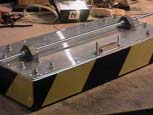
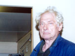
11.9.2006
Even if the film with the finished welded frame is still inside my camera, I have at least some pictures of Mr Taubert, the building fitter, who has done most of the welding work.
Watch photos |
|
|
|
| |
 |
|
11.9.2006
In the meantime, I've also built a vinyl chassis for the touchscreen display.
Watch photos |
|
|
| |
| |
|
|
|
11.9.2006
While the ATMega8 wheelchair code from 23.5. is quite old now, this is the actual code, that I am using. It is not really new, it is not yet finished, but it is something to work with.
Download "readout32ldu_grafikterminal8.bas" |
|
|
|
|
|
| |
| |
 |
|
19.9.2006
Volker already proposed a block diagram for the wheelchair electronics on 14.8. Now, I just wanted to insert the missing distance measurement sensor - quick and dirty with a pen - into his drawing. But then, I decided to redraw the whole thing, because his version was only for the entertainment controller and I thought, it might be useful to have a diagram for the whole wheelchair electronics, including the drive control stuff and including the interface to Galleryzone.
Download the new block diagram (PDF)
Download Volkers block diagram proposal from 14.8. (PDF) |
|
|
| |
|
|
|
| |
 |
|
20.9.2006
During the last weeks, I worked a lot on the final shape of the wheelchair. And today, I picked up all the photos from the drugstore, that I've taken during that time, and I scanned the best of them.
Watch photos |
|
|
|
| |
 |
|
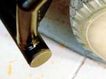
4.10.2006
Because I didn't like the open tubes of the frame, I've built some plastic caps for them out of Fimo.
Watch photos |
|
|
|
| |
 |
|
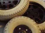
29.10.2006
Have a look at the new racing tires that I've put on my wheelchair's wheels, now.
Watch photos |
|
|
|
| |
 |
|
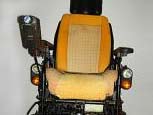
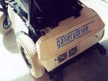
29.10.2006
During the last three weeks, I've built the car body out of vinyl. This was much more work, than I expected, but finally, it looks really good!
Watch photos |
|
|
|
| |
 |
|
29.10.2006
To avoid, that I always photograph the wheelchair from the same angle, I had the idea to make a 360° viewer. The pictures were shot with my analogue camera, so don't wonder if it shakes and flickers a bit. And because I've taken the photos at 2 o' clock during night, the rotation of the wheelchair is probably not as precise as you might expect. On those pictures, you can't see the final shape, because the box for the controlling circuit and the display is still missing. This will make it look even better.
Run 360° viewer |
|
|
|
| |
 |
|
31.10.2006
In order to buy some more cheap electric wheelchairs, I did a little bit of research. I wanted to find out, at which time of the year, the market for used wheelchairs is mostly saturated.
Read more and watch diagram |
|
|
|
|
|
|
| |
 |
|
2.11.2006
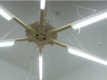
Today, I had an overheating problem at the inverter of the cold cathode tube of the LDU! Please take care, that you don't get the same problem.
Read more and watch photos |
|
|
| |
| |
 |
|
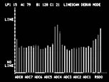
3.11.2006
GDdoctor Pro V0.9 is out! Based on the idea, to show what the sensors see as bar graphs, Tilman developed GDdoctor. Now, I've written an entirely new tool, GDdoctor Pro, which also records what the sensors have seen. And it has some more features to help adjusting the "out of line" recognition.
Of course, I had to do some changes in the drivecontrol Bascom code, to let the controller send the data, that GDdoctor pro requires. Everything which is not related to rs232 output is still the same as in the code from 11.9.
GDdoctor Pro download, screen shot and manual
Download new drivecontrol Bascom code |
|
|
| |
| |
 |
|
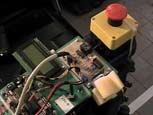
4.11.2006
I have done some minimal changes at the drivecontrol boards from 6.7. Now, there is a connection for the emergency off button onboard. It breaks the 24V control voltage supply for the motor driver. So, pushing the emergency off will stop the wheelchair immediately but it will not shut down the microcontrollers.
The other change is, that I've taken the former serial input as speed control input #3, which connects the Atmega8 to the entertainment controller.
Download new circuits (PDF) |
|
|
|
| |
 |
|
5.11.2006
There's a new test drive video online! Check out, how the wheelchair looks in motion, with its new body.
Watch video |
|
|
| |
|
|
|
| |
 |
|
9.11.2006
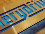
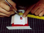
To label certain parts of the vehicle, I've cut some stickers. And I made use of the delayed-action shutter release feature of my camera to take some pictures of me, cutting those stickers.
Read more and watch photos |
|
|
|
| |
 |
|
9.11.2006
You have seen the result of this work already in the video from 5.11. But if you want to have a closer look on how I've built the elektrobox, watch this analogue photo series. (Again, I've taken those pictures with my old chemical based Nikon - and that's the reason, why it took so long to upload them.)
Read more and watch photos |
|
|
|
| |
 |
|
12.11.2006
I just finished the layout and the soldering work of the entertainment board. Please wait a bit until you also start soldering it, because I haven't checked if it works, yet.
Download layout (PDF)
Scans of the board |
|
|
|
| |
 |
|
7.12.2006
Concerning the diary updates, I was very lazy during the last weeks. So today, I'll post a lot of stuff. Let's begin with my burnt power supply.
Read about the burnt voltage supply |
|
|
|
| |
 |
|
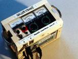
7.12.2006
In the meantime, I've built a second service control unit. Seen from the technical side, they both do the same thing. But there's still a difference, which makes it quite comfortable to have them both.
Read more and watch photos |
|
|
|
| |
 |
|
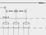
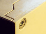
7.12.2006
With the third control board installed in the Gallerydrive car, I also set up all the communication between the Galleryzone and the car. It is time now, to define the positions at the car, where IR transceivers, IR distance sensor and the retro reflecting foil are located.
Read more and watch plan and photos |
|
|
|
|
|
|
|
|
|
| |
 |
|
7.12.2006
Another extra device, which is required for the Galleryzone system, is the queue controller. This does not need to be interconnected with the zone devices, that I've described above. I've built one with its own power supply and some extra features. As I still want to do some minor changes at its code, I'll post the schematics and the code, when the device is finished.
Read more about the advanced queue control unit |
|
|
|
| |
 |
|
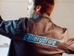
7.12.2006
I also produced the first Galleryfashion item. Because we'll need some affordable stuff to fill the museum shops with.
Watch Galleryfashion work wear |
|
|
| |
|
|
|
| |
 |
|
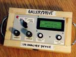
14.1.2007
A few weeks ago, I've built this I/O analyze device. And now, I am sitting in the train to Nuremberg, where I will have to finish a video for adidas, that I've directed. If you have ever wondered, how I am financing this whole project, now you know it. Because there are some hours time now and nothing better to do, I will describe this handy device for you.
Watch photos and read description
Download analyze device Bascom code |
|
|
|
| |
 |
|
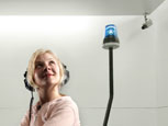
17.1.2007
Finding the right amplifier for the headphones, was along search. Even if I am not totally happy with the result, I have written down the story, during my way back to Berlin. (The video for adidas is finished and the client is happy! - So at least I have enough money for the next months to go on with working on the project.) However, the amp is still a part of the wheelchair, which is worth to improve. But I've spent very much time in that now, and furthermore, it is a part, where I've never expected any problems. So for the moment, I will let it be like it is.
Watch photos and read the whole story |
|
|
|
| |
 |
|
17.1.2007
The total code and circuit update!
Now, in the train, I also have enough time, to put all the new codes and circuits online. Concerning the drivecontrol code, I have to say, that the odometer stuff is now implemented. Practically, that means, that the wheelchair is now also able to drive at very low speeds, if there's a heavy person sitting on it. This is definitely important at some situations, which I already have in my mind. (But I am too lazy at the moment to explain those plans in detail.) Another interesting thing is, that I've found out during my tests, that the EEPROM of the Atmega8 is not very reliable. Since it stores all the calibration values, that is a very important safety issue. Wrong calibration values can easily lead to a situation, where the wheelchair detects the line at a wrong position. And then, it will move in an unexpected way. So what I've done in the new version is, that I've stored those calibration values twice at different positions of the EEPROM. During each program cycle, the program will compare those values and if they are not equal, it will stop and display an error at the error output. When I mention the error messages already: I've implemented some of them. The different errors will be displayed as a morse code like blinking alert output. The alert output will switch to high for 0.3 seconds - for several times with a 0.4 seconds break in between. You'll have to count, how often it switches on - and this is the error number. As end signal, it will switch to high for 1.5 seconds.
Here is a table of the different drivecontrol errors:
Error #1: Unexpected value from ADC's (0 or 255). / Check electronics!
Error #2: Unexpected value from calibrated LDU (value is below black or above white). / Check calibration and check track (this could also be a reflecting floor, perhaps?).
Error #3: EEPROM memory error (both stored calibration values in the EEPROM do not match)! / Calibrate again.
Another thing, that you can find in this diary entry, is the layout of the entertainment control board. Most of it is tested and works. There are two things, which I haven't tested up to now, since I am not using them, yet: The digital poti for the microphone and the rs232 feedback from the mp3-player.
And of course, there's also a new version of GDdoctor pro, the drivecontrol analyze software, which works with the new drivecontrol code.
Download layout of the entertainment controller (PDF)
Download entertainment controller Bascom code
Download entertainment controller scan - upper side
Download entertainment controller scan - lower side
(This service is especially provided for the grass smokers amongst us.)
Download drivecontrol Bascom code
Download GDdoctor pro Processing code (zip) |
|
|
|
|
|
|
| |
 |
|
25.1.2007
I mentioned already in my entry from 17.1., that I might upload some more pictures of the amplifier modules. Well, here they are!
Watch photos |
|
|
|
|
|
|
|
|
|
| |
 |
|
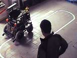
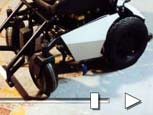
25.1.2007
Yesterday, I've filmed the test run video #5 - and I guess, that this will be the last test drive video. Everything worked quite well. In this film, you can see, how the wheelchair behaves in a course with zone system. So, I would also say that this diary is finished for the moment. I'll start to work on the robotik room tomorrow. But if I still do some important changes on the car, I'll write them down, here.
Watch video |
|
|
|
|
|
| |
|
|
| |
|
|
 |
|
 |