|
|
||
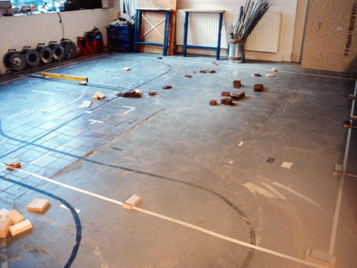
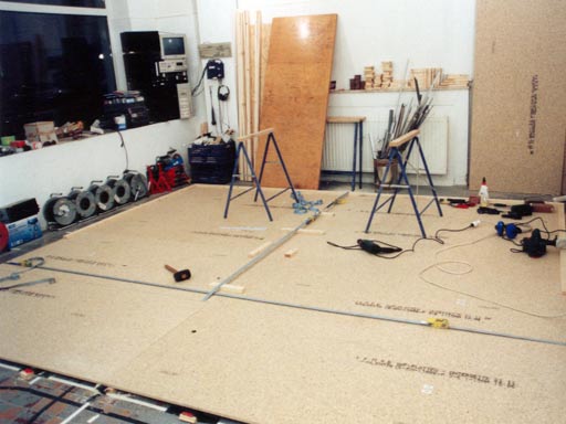
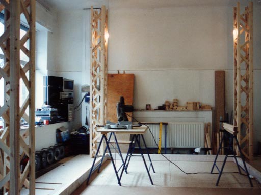
| Back to the diary | The very first step for building the room, was to adhere its dimensions with white adhesive tape on the floor. The space in my workshop is very tight for what I want to build. So it is important, that I start to build the machine at the right place. I've drawn some plans, and according to them, some moving walls will pass the heating by only four centimeters. You see: Space is rare, here. And since the workshop is also the place, where I live, the next months will get slightly uncomfortable (except if you prefer to live inside an unfinished artwork). |
|
|
||
After marking the dimensions, I had to level the space, where I'll set up the room. |
||
|
||
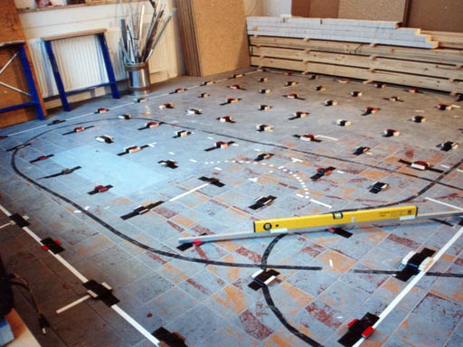
I've built 64 little towers out of wood and cardboard to get an even surface. During that process, I found out, that the height of my floor differs to up to five centimeters. It's easy to imagine, that it is less work, to level this floor once, than rebuilding the undulating surface of my floor in every place, where I want to set up this piece, later. |
||
|
||
Now, the height of the "towers" only differs to up to half a millimeter. |
||
|
||
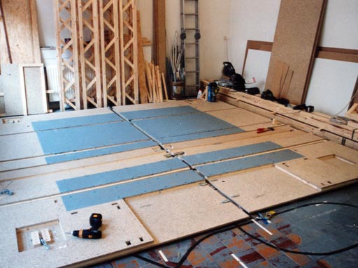
On the leveled floor, I started to build the fundament. This consists out of two layers of flake board with wooden slats in between. I will also use the space between the two flake boards to let electric cables and wire rope run there. On the image below, you can see the first layer of flake boards. |
||
|
||
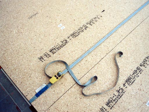
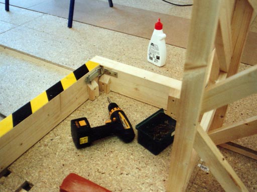
To drag the boards perfectly together, I used some lashing straps. |
||
|
||
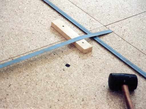
And after dragging them together, I fixed their position with wooden slats, that I screwed onto them. They will be removed later, because the whole construction has to be easy to disassemble (you remember: constraint #1). In fact, all the parts of the fundament will get a robust tongue and groove joint, which I'll build with the slats. You'll see this later. |
||
|
||
In the middle of the construction, you can already see the fundament for the slider. Due to several reasons, I won't build the rotating disc, that you might have seen in the video, but a slider to let the car drive circles inside the room. |
||
|
||
The animation below explains the functionality of the slider in the room. Push "play" to run the animation. |
||
|
||
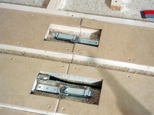
Inside the slider's fundament, you can also see, that all the boards are dragged together with clasps. There's also a XLR connection for the slider's end switches. The material for the surface of the slider and for the slider itself is MDF, because this material has a very low friction. |
||
|
||
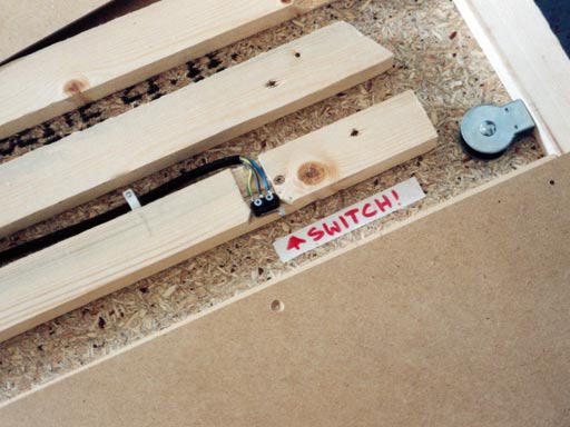
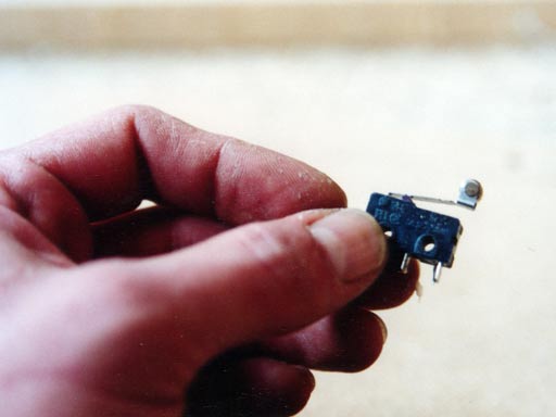
Here, you can see one of the slider's end switches. I've mentioned this switch already above. First, I took a normal micro switch because its electrical characteristics fit alright to the purpose. |
||
|
||
Later, I thought that even if the electrical characteristics fit, it might be simply too tiny for the mechanical duty, that it has to fulfill. When the room works, quite a heavy sheet of wood will crash into it, with quite a speed. And this will happen very often. So, maybe its mechanical characteristics don't fit too well. |
||
|
||
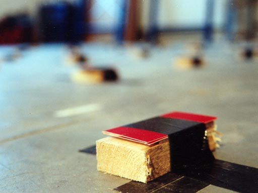
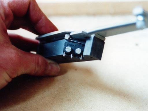
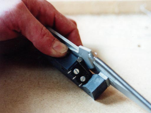
At the end, I decided to build a stronger switching mechanics out of vinyl. This device is built for heavy duty, now. It doesn't matter anymore, how heavy or fast the wood is, that switches it. As you can see in the image below, a push on the switch simply turns one piece of vinyl. After releasing it, it is dragged back by a steel spring. |
||
|
||
Attached to this vinyl construction, there's still the old micro switch. Pushing the sheet of vinyl will turn the sheet in the middle... |
||
|
||
...and the micro switch will be pushed by the thickness of this vinyl sheet. |
||
|
||
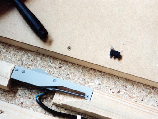
Here, I have already screwed the new construction into the slider's fundament. For comparison, you can also see the plain micro switch above. The part below suits definitely better to what I want to do. |
||
|
||
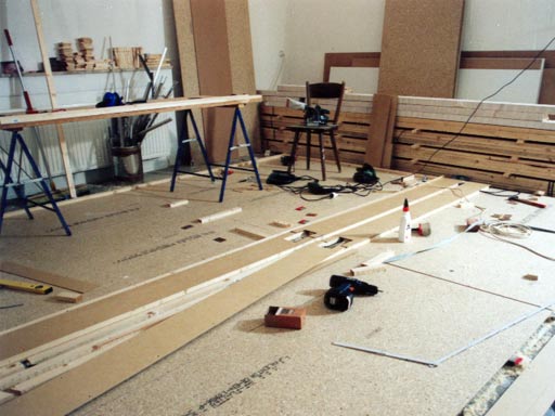
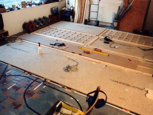
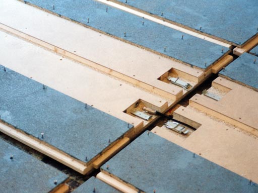
The work on the fundament goes on. In the front, there are still plain flake boards. Behind that, there's the slider fundament with the slider already on top. In the back, you can see, how the boards look inside. The wooden slats, that surround each board are used as tongues and grooves. Inside of each board, there are several pieces of wood, which keep the distance to the upper flake board. Between the woods, there's plenty of space for additional cables. |
||
|
||
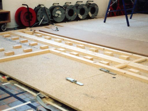
On this picture, the boards in the back are almost finished. In the front, there's a part without those wooden blocks. Here, I'll insert a ramp for the car at the end. |
||
|
||
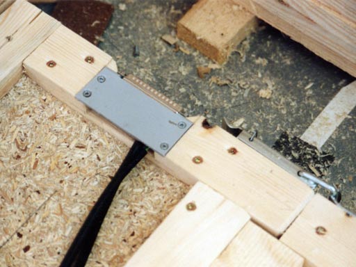
This close up shows the sub-d connection, that will be used for the end switches and for other electronics that might be inserted later. On the right, you can see another clasp. Those clasps go around the whole fundament and drag the boards together. |
||
|
||
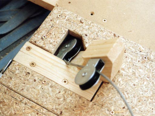
The slider will be moved to one direction by a motor winch, and to the opposite direction by a counter weight. The force will be transmitted via wire ropes, which go over pulleys. |
||
|
||
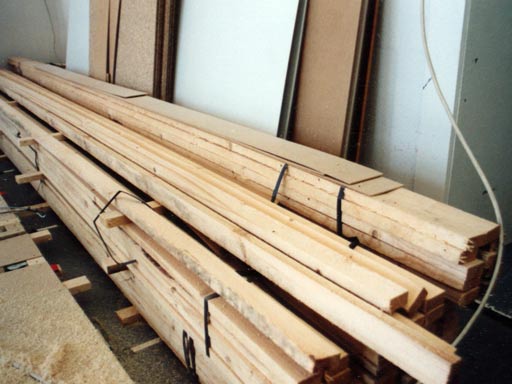
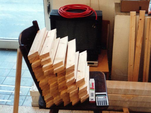
My wood stock shrinks. |
||
|
||
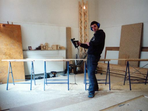
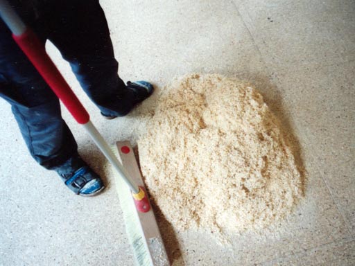
Because the wood, that I've ordered was the cheapest that I could get, it also doesn't look too good. So I've invested some money in a planing machine, and now I am planing every slat before I use it. The advantage of this is, that I can plan them all to exactly the same size. (Those cheap slats differ in their size quite strongly!) And that means, that all the parts fit better together at the end, even if this is quite a lot of loud and stupid work, ... |
||
|
||
... which also produces much dirt. |
||
|
||
I guess, that I've used some of the slats above for the pieces, that are shown beyond. They will be used to build the trusses, which will hold the room, later. |
||
|
||
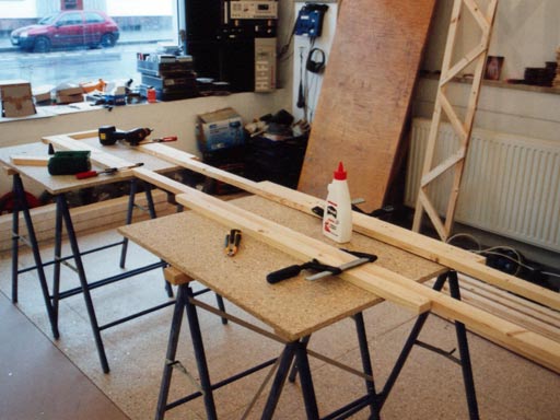
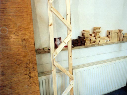
To build the trusses quick and precise, I've made a helping construction. Inside this template, I will build the four sides of each truss. In the background, you can already see one finished piece far a traverse, leaning at the wall. |
||
|
||
Here's a close-up of how I've built the parts. With screw clamps, I fixed two slats in a parallel position. And then, I glued the short slats onto them. The short slats are also fixed with two screws, each. But the screws' function is primary to hold the wood in position during the gluing. |
||
|
||
Here's another finished part for one of the trusses. |
||
|
||
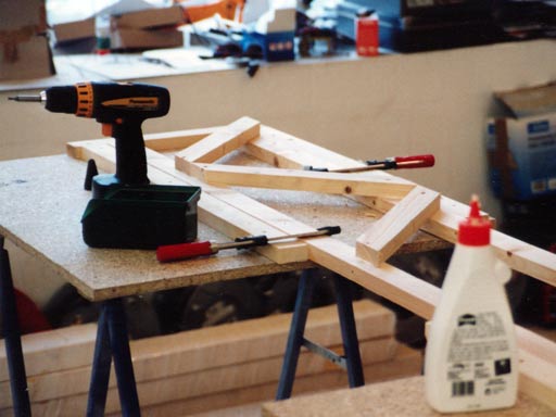
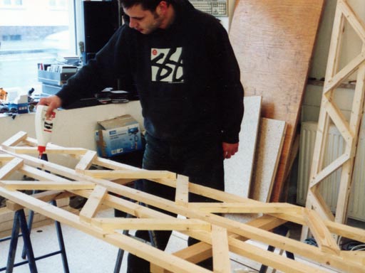
Now, I have to glue the four truss parts together. Again, I will fix them with screws during the gluing. |
||
|
||
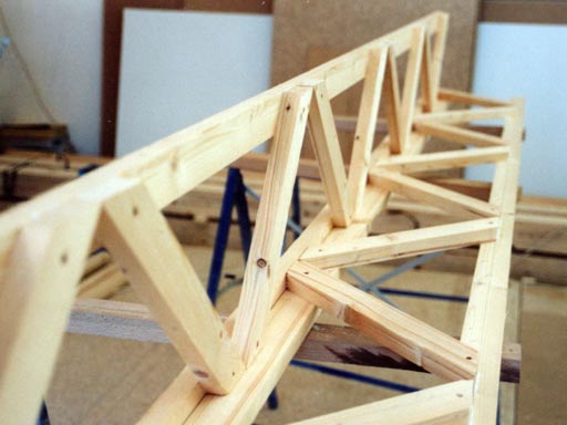
Now, it already starts to get a nice shape. |
||
|
||
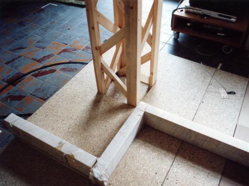
Each truss finally stands in a cavity, which is omitted in the upper boards of the fundament. |
||
|
||
Ok, and this is how the construction with the four trusses looks like. The frame on the floor is a barrier, which avoids that the car (if it would freak out) crashes into one of the trusses. |
||
|
||
The barriers will simply be plugged into the fundament boards. Some more clasps will fix them. The reason, why I use all those clasps is simple: I want to build the whole room in a way, that a rubber hammer is required as the only tool to set it up. And I also want to try to build it in a way, that the whole setup can be done by just one person. Let's see, if that works out! |
||
|
||
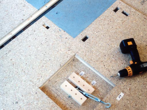
Inside each cavity, there are turnbuckles, which drag the trusses into the cavities. The gray area is the floor inside the room. |
||
|
||
When I painted the floor, I used liquid plastic for that. This gives a nice robust surface, but the thinner in the liquid plastic is fucking strong. So my workshop smelt extremely during the last days and I really felt bad. When the smell was too strong, I opened all doors and windows - but an outside temperature of 12°C also doesn't make this too comfortable. Living in that workshop was quite hard during that time. However, I'm very happy, that this is over now. As you can see, I've turned out all the screws during the painting - because I did not want that their heads get stuck with the liquid plastic. |
||
|
||
I also took all the boards apart, that the plastic does not stick the different parts together. |
||
|
||
Here's another nice part of the fundament: The wire rope of the slider, that leads to the counterweight, comes out here. |
||
|
||
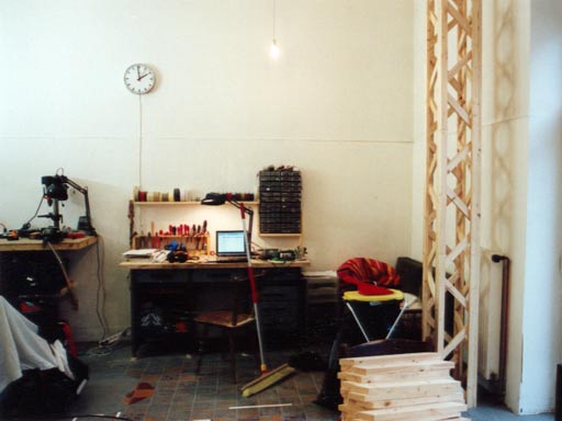
My laptop is running most of the time, when I am building, because all the plans are on its hard disk. I never printed them out. |
||
|
||
And if you have a closer look on the computer, you can see that it suffers a loot. Poor electronic brain. |
||
|
||
|
|
Please note, that the content on this webpage is licensed under a Creative Commons Attribution 2.0 License. Please respect the copyright of other webpages' content, which are linked from this webpage. |
|